- Blog/
Rust, FPGAs, and Seven Segment Displays
The title of my third year project is “Programmable I/O for Flexible Interfaces in Embedded RISC-V Systems”, which basically just means making something very similar to the Programmable I/O blocks on the Raspberry Pi Pico (which I think are insanely cool), and then integrating them with a RISC-V core to create a simple microcontroller that can interface with basically anything at fairly low power. This means a lot of work with FPGAs and Verilog/HDL which are two things I don’t have much experience with.
I did do an introductory digital systems design course as part of my degree last year, and learned a bit about Verilog and FPGA design & architecture. The coursework was making a video game (a very common application for FPGAs, of course), and our shitty asteroids clone was mostly thrown together in one very long week of late nights spent fighting with Xilinx Vivado, the FPGA IDE and toolchain, and also perhaps the worst piece of software ever. However, going from making an arcade game to a microcontroller is a big leap that’s going to require a lot of learning.
So instead of revising for my exams, I spent a few days trying to get to grips better with Xilinx’s design tools and FPGA work in general by designing a hardware interface for a seven segment display, integrating it with an existing RISC-V core, and then writing a software driver for it in Rust.
Getting Going #
My staring point was this GitHub repo, which was basically perfect because it provides a RISC-V SoC with UART, Ethernet, an SD card controller, and scripts to build bootloaders and the Linux kernel. It was literally as easy running make as per the instructions, flashing the kernel onto an SD card, and then connecting over the serial port. I had Debian up and running on the Nexys A7 board the School of Engineering had kindly let me borrow with surprisingly little difficulty. The Vivado block design of the SoC is shown below, it’s just a core hooked up to the onboard DDR2 memory and a few I/O components using AXI buses.
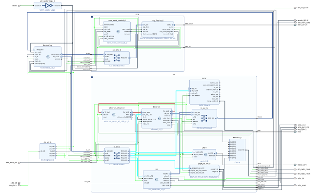
The CPU core used is Rocket Chip, an open-source RISC-V SoC generator built and maintained by UC Berkeley Architecture Research. Rocket Chip can generate a RTL RISC-V implementation that has virtual memory, a coherent multi-level cache hierarchy, IEEE-compliant floating-point units, and all the other bits and bobs you need for a useful CPU. All the HDL is entirely parametrised, so can be customised to generate whatever kind of core takes your fancy. It’s written in CHISEL, a HDL embedded in Scala, which is what enables this. Scala for HDL sounds cool (read: better than Verilog, which is not much competition), and I really want to try it out at some point.
Linux running on an FPGA was cool, but I didn’t do much with it besides brag about it on IRC.

Instead, I went back and compiled the bare metal example because Linux was super slow, and writing bare metal drivers is much simpler than Linux drivers (part 2, perhaps?). The example is just sending hello world over the serial port by writing to the UART registers, but the key bit is the linker script and startup code, which will come in handy later. The more observant among you will notice one problem with this code though…
Crab Time #
It’s written in C, so obviously it needed the Rewrite It In Rust treatment. My idea was to create a minimal no-std executable using the riscv-rt crate, which is meant to provide a startup and runtime for embedded RISC-V targets. Of course, it couldn’t be that simple, and I ended up spending the best part of a day grappling with rustc/lld to generate me an executable that would run, all to no avail. I probably tried every command line flag and cargo configuration parameter in existence, but could not for the life of me get anything to work using riscv-rt . My hacky solution in the end was to just compile a rust crate without riscv-rt to a static library exposing only main, and then invoke the GCC cross-compiler to link using the linker script and startup assembly code from the example. This worked without any trouble, and I had Rust code running on an FPGA!
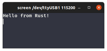
The serial interface code is shown below. The hardware has 4 registers: Rx, Tx, and control and status registers. I can’t find much documentation on how to use the control/status registers besides the example code, but the idea is simple enough: put some bytes in the Tx register, and it gets sent to the console on the other end.
pub struct Serial(&'static mut UartRegs);

#[repr(C)]
struct UartRegs {
    rx_fifo: RO<u32>,
    tx_fifo: WO<u32>,
    status: RO<u32>,
    control: RW<u32>,
}

impl Serial {
    pub unsafe fn new() -> Self {
        Serial((UART_ADDR as *mut UartRegs).as_mut().unwrap())
    }

    pub fn write_byte(&mut self, byte: u8) {
        while (self.0.status.read() & SR_TX_FIFO_FULL) != 0 {}
        unsafe { self.0.tx_fifo.write(byte as u32) }
    }
}
I’m using volatile_register, which provides read-only, write-only and read-write cells with volalile access for modelling CPU registers. Rust really shines here, as I can encode what functions are read-only and what requires a write in the type system, and through the use of immutable vs mutable references. Writes are also effectful, so require unsafe blocks, whereas reads do not. The #[repr(C)] is needed as Rust makes no guarantees on struct layout, so we need to tell the compiler to lay the data out in the way C would (which is the way you would expect) to be able to just cast our address to a *mut UartRegs and it work.
The Display Controller #
So I had the bare minimum working, it was time to extend it with something a little more exciting. The 7 segment display on my board has a hardware interface that looks like the following:
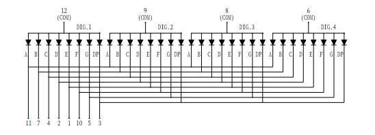
Each digit has it’s own common anode, and all the same segments on each digit share a pin. This means it’s fairly easy to write a controller which controls all the digits in unison: tie all the anodes high, and then work out what patterns of segment signals correspond to each digit. In Verilog, that’s a simple behavioural case statement:
always@* begin
    case (number)
        // lots of bit patterns
        4'h0: digit = 7'b1111110;
        4'h1: digit = 7'b0110000;
        4'h2: digit = 7'b1101101;
        4'h3: digit = 7'b1111001;
        4'h4: digit = 7'b0110011;
        4'h5: digit = 7'b1011011;
        4'h6: digit = 7'b1011111;
        4'h7: digit = 7'b1110000;
        4'h8: digit = 7'b1111111;
        4'h9: digit = 7'b1111011;
        4'ha: digit = 7'b1110111;
        4'hb: digit = 7'b0011111;
        4'hc: digit = 7'b1001110;
        4'hd: digit = 7'b0111101;
        4'he: digit = 7'b1001111;
        4'hf: digit = 7'b1000111;
    endcase
end
Controlling each digit individually is a bit harder, as the segments are all connected together. The way to do it is to strobe the anodes, having only one of them active at a time and displaying the segment pattern that we want, but strobe it fast enough that our eyes can’t tell that only one digit is on at a time. The onboard clock is 100MHz, so we use a 20-bit counter to slow that down to a much more tame ~100Hz, and select which of the 8 digits is active.
//divide the 100mhz clock to something a little slower
reg [19:0] clk_count = 20'd0;
always @ (posedge clk) clk_count <= clk_count + 1'b1;

//use most significant 3 bits to count which LED is active
wire [2:0] active_digit = clk_count[19:17];
For those of you not familiar with verilog:
reg [19:0]defines a register that is 20 bits wide20'd0is a numeric literal that is 20 bits wide, specified in decimal, with the value 0- Yes, really, that’s the syntax.
always @ (posedge clk)defines a circuit that is rising edge-triggered<=is non-blocking register assignmentclk_count[19:17]is a bitwise slice of the most significant 3 bits of the registerclk_count
Rather counterintuitively, the anodes and digits are both active low. I didn’t figure this out until I’d spent an entire weekend debugging everything instead of just reading the docs 🙃.
Writing a simple verilog module to act as a controller was the easy part, integrating it with the existing SoC was the challenge. All the other I/O blocks are connected over an AXI4 bus, which is fairly simple to extend. AXI-4 is a bus interface specification developed by ARM as part of the AMBA (Advanced Microcontroller Bus Architecture) specification, it’s a transaction-oriented master-slave interface with 5 channels. There are 3 types of AXI-4 interface:
- Full AXI, for high performance memory mapped I/O
- AXI-Lite for simpler, low throughput memory mapped registers
- AXI-Stream, for high speed streaming data
I went with AXI Lite, as all I was connecting was 8 registers (one for each digit). Vivado includes a “wizard” to generate a template for an AXI IP block, so it created a new project for me with a top level module defining an AXI interface, and very kindly pointed out where to insert my own port and module instantiations. I instantiated my module and connected the bus registers to the display controller, and then added two new output ports to the block, anode[7:0] for the 8 anodes and seg[6:0] for the 7 segments.
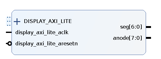
(The three input ports are clock, reset, and the AXI bus connection, which Vivado handles all the internal wires for.)
Adding my new IP to the design was relatively painless, just a few steps in the block diagram GUI to drop it in and connect the wires up. I had to also extend the I/O address space to memory-map my registers, and add a new constraints file to connect the output from the design to the peripherals. Constraints files contain information about the physical properties of the design (clocks, I/O, timing), and in this case they’re used to connect the right wires on the design to the correct physical output pins on the FPGA chip.
To verify this worked I used Xilinx System Debugger (xsdb) to connect to the FPGA, which provides a neat little command line interface where you can poke and prod at running targets on an FPGA or Xilinx SoC. I manually wrote into the address I’d mapped the registers to to verify that everything worked, which it did (after I remembered that the anodes were active low and fixed that).
More Rust #
So the hardware works, but what about software? Writing a driver for the display device was fairly simple, just define an array of 8 registers and wrap it in a struct, and we can use the same pointer-cast technique from earlier to create the device.
type DigitRegs = [RW<u32>; 8];

#[repr(C)]
pub struct Display(&'static mut DigitRegs);

impl Display {
    pub unsafe fn new() -> Self {
        Display((DISPLAY_ADDR as *mut DigitRegs).as_mut().unwrap())
    }

    pub fn take() -> Option<Self> {
        singleton!(:&'static mut DigitRegs = unsafe {
            (DISPLAY_ADDR as *mut DigitRegs).as_mut()?
        })
        .map(|regs| Display(regs))
    }
}
The intended way to get an instance of the struct is through the take method. It makes use of the singleton! macro from the riscv architecture crate, that will return a Some(T) the first time it is called, but a None every time after that. This ensures that we only have one instance of our peripheral struct, which prevents multiple concurrent accesses leading to race conditions, etc. We use it to create a &'static mut DigitRegs from a pointer to the address where they are, and then wrap that in a struct to create the display device. It’s a neat little bit of unsafe rust, and we’re still trying to use the type system to our advantage to enforce safety.
I wanted to implement the Index and IndexMut traits for Display, but this turned out to not be possible. The Index trait looks like this (slightly simplified, and with lifetime annotations added):
pub trait Index<Idx>{
    type Output;

    fn index<'a>(&'a self, index: Idx) -> &'a Self::Output;
}
Index has to return a reference, the lifetime of which is the same as the lifetime of self. In this case, that would be 'static. However, under the hood, our data is accessed using ptr::volatile_read, which returns T, not &T or &mut T. We can’t actually get a reference to the data in our registers safely, so we can’t satisfy the requirements for Index. Or IndexMut. Instead, I settled for boring old fn get(&self, idx: usize) -> u32 and fn set(&mut self, idx: usize, val: u32).
With the API all set up, I wrote a little demo program that rotated the digits 0-9 across the display, which is what’s running in the gif from further up.
//init the 8 digits
for i in (0..8).rev() {
    display.set(i, i as u32);
}

loop {
    //shift all the digits along
    for i in (1..8).rev() {
        display.set(i, display.get(i - 1));
    }
    //set the last digit to 1+ the prev value
    display.set(0, (display.get(0) + 1) % 10);

    //write the digits to the serial device too
    for i in 0..8 {
        serial.write_byte(display.get(i) as u8 + 48);
        serial.print(" ");
    }
    serial.println("");

    delay.delay_ms(1000);
}
Conclusion #
This was a really fun little project, getting to play around with loads of different aspects of embedded and digital systems design that I’m interested in, and that I’m going to be doing more of next year. There was a lot of trial and error, poring over Xilinx documentation, and fighting Vivado (when it wasn’t crashing), but its those kinds of experiences where you often end up learning the most. It really didn’t come together anywhere near as cleanly as I’ve probably made out.
There’s a lot more I want to explore too. CHISEL seems super interesting, I like the idea of using a functional language to build circuits (with an actual type system to enforce design constraints). I also barely scratched the surface with AXI, and Vivado did most of the work for me: I’ll need to be a lot more familiar with it for designing more complex I/O devices, especially AXI-Stream for the kind of high throughput design I have in mind.
I also want to thank Eugene Tarassov for the GitHub repo that provided the block design and scripts for the RISC-V SoC. I wouldn’t have had a clue where to even start without that, and it will probably end up being the starting point for my actual project